Introduction

Measuring acceleration is a critical aspect in various fields, including automotive, aerospace, and robotics. Traditional methods for acceleration measurement often rely on accelerometers, which can be bulky and expensive. This article presents an innovative electric circuit (Figure 3.2) that leverages the change in capacitance to measure acceleration with high precision and low cost.
Circuit Operation
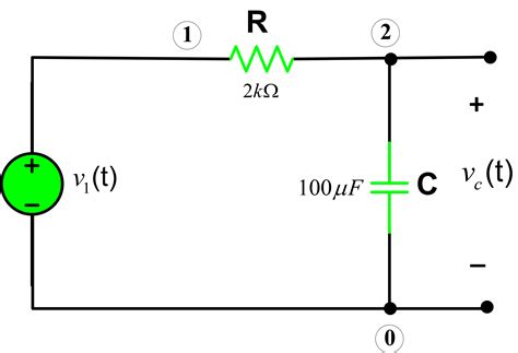
The circuit operates on the principle that acceleration causes a change in the distance between two conductive plates, thereby altering the capacitance. The circuit consists of a capacitor (C), a resistor (R), a voltage source (V), and a voltmeter (Vout).
When an acceleration is applied, the conductive plates move relative to each other, resulting in a change in capacitance. This change in capacitance affects the charging and discharging time of the capacitor, which can be measured using the voltmeter. By calibrating the circuit, the measured voltage can be directly related to the acceleration.
Capacitance Change due to Acceleration
The capacitance of a capacitor is directly proportional to the area of the conductive plates (A) and inversely proportional to the distance between them (d). When an acceleration (a) is applied, the distance between the plates changes by an amount Δd. The change in capacitance (ΔC) can be calculated using the following equation:
ΔC = εAΔd / d²
where ε is the permittivity of the material between the plates.
Voltage Measurement and Acceleration Calculation
The change in capacitance affects the charging and discharging time of the capacitor. The time constant (τ) of the circuit is given by:
τ = RC
When the capacitor is charged, the voltage across the capacitor (Vout) changes according to the following equation:
Vout = V(1 - e^(-t/τ))
By measuring the voltage across the capacitor at a specific time (t), we can calculate the acceleration (a) using the following equation:
a = (Vout - V) / (εA(V - V0)t² / R)
where V0 is the initial voltage across the capacitor.
Applications
The electric circuit presented in Figure 3.2 has numerous applications in fields where acceleration measurement is crucial. Some examples include:
- Automotive: Measuring acceleration for vehicle stability control, anti-lock braking systems, and airbag deployment.
- Aerospace: Monitoring acceleration during aircraft maneuvers, spacecraft launches, and satellite deployments.
- Robotics: Determining acceleration for robot motion control, navigation, and collision avoidance.
- Medical: Measuring acceleration for gait analysis, balance assessment, and fall detection.
- Industrial: Monitoring acceleration for vibration analysis, condition monitoring, and process control.
Advantages and Disadvantages
Advantages:
- Low cost: The circuit components are inexpensive, making it an affordable solution.
- High precision: The circuit can measure acceleration with high accuracy and repeatability.
- Compact size: The circuit can be integrated into small devices and systems.
- Real-time measurement: The acceleration can be measured in real-time, providing immediate feedback.
Disadvantages:
- Temperature sensitivity: The capacitance of the capacitor can be affected by temperature changes, which can impact the accuracy of the measurement.
- Limited range: The measurement range is limited by the physical dimensions of the capacitor and the maximum voltage applied.
- Sensitive to external noise: The circuit can be susceptible to electrical noise, which can interfere with the voltage measurement.
Common Mistakes to Avoid
- Improper calibration: The circuit must be calibrated using a known acceleration value to ensure accurate measurements.
- Inappropriate capacitor selection: The capacitor used must have an appropriate capacitance range and dielectric material for the desired acceleration measurement.
- Incorrect voltage measurement: The voltage measurement must be performed with a high-impedance voltmeter to avoid loading effects.
- Environmental influences: The circuit should be protected from temperature changes and external noise to maintain measurement accuracy.
Frequently Asked Questions (FAQs)
-
What is the maximum acceleration that can be measured using this circuit?
– The maximum acceleration is limited by the physical dimensions of the capacitor and the maximum voltage applied. Typically, it can measure accelerations up to several g-forces. -
How does temperature affect the accuracy of the measurement?
– Temperature changes can alter the capacitance of the capacitor, potentially affecting the accuracy of the measurement. Compensation techniques or temperature-stable capacitors can be used to minimize this effect. -
Can this circuit be used for measuring both positive and negative accelerations?
– Yes, the circuit can measure both positive and negative accelerations. The direction of acceleration is determined by the change in capacitance relative to the initial capacitance. -
What are some potential applications of this circuit?
– The circuit has applications in automotive, aerospace, robotics, medical, and industrial settings where acceleration measurement is required. -
How can the circuit be integrated into a larger system?
– The circuit can be easily integrated into a larger system using a microcontroller or data acquisition device for signal processing and data logging. -
What are some alternative methods for measuring acceleration?
– Alternative methods include accelerometers, inclinometers, and gyroscopes. Each method has its own advantages and disadvantages, and the choice depends on the specific application requirements. -
Can the circuit be used in real-time applications?
– Yes, the circuit can be used in real-time applications. The voltage measurement can be performed at a high sampling rate to provide immediate feedback on the acceleration. -
What is a novel application idea for this circuit?
– A novel application idea is to use the circuit to measure the acceleration of a human in freefall to estimate their height.